


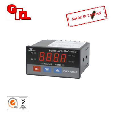
PWA-6065 POWER CONTROLLER/MONITOR
POWER
CONTROLLER/MONITOR
Model : PWA-6065 ISO-9001, CE, IEC1010
FEATURES
- Professional WATT meter with standard DIN case ( 96 x 48 mm ) and Control/Alarm function.
- Microprocessor circuit ensures high accuracy and provide special functions and features.
- Large red LED display, high brightness and easy to read.
- Measurement range ( no cooperate the external CT and the PT ) :
Watt : 0 to 6,000 Watt. - Input signal ( without PT, CT ) :
ACV : 0 to 600 ACV, 40 to 400 Hz.
ACA : 0 to 10 A, 40 to 400 Hz. - True rms for WATT measurement.
- Current input can cooperate the external CT ( current transformer ) such as CT 1000/5A, CT 100/5A ...to expend the measurement range. The CT range can be adjusted with default.
- Voltage input can cooperate the external PT ( voltage transformer ) to expend the measurement range. The PT range can be adjusted with default.
- Control setting, Hi/Lo alarm setting.
- Control relay output, alarm relay output.
- Control Relay will make action when the reading value reach to control value.
- Alarm Relay will make action when the reading value reach to high/low alarm value.
- Hysteresis value setting for control and alarm function.
- Power : 90 ACV to 264 ACV, 50/60 Hz.
- RS232/USB computer interface.
- Option data acquisition software.
GENERAL SPECIFICATIONS
Display | Large LED display. 4 digit LED. 14 mm ( 0.55 inch ) digit height. 6 indicators. PV ( process value ) indicator SV ( set value ) indicator Control out indicator Alarm out indicator Watt indicator KVA indicator | ||
Circuit | Custom chip of microprocessor LSI circuit. | ||
VA measurement | 0 - 6,000 W. * True power * w/o PT. CT. | ||
Input signal | ACV : 0 to 600 ACV, 40 to 400 Hz. ACA : 0 to 10 A, 40 to 400 Hz. * w/o PT. CT. | ||
Sampling Time | Approx. 0.8 second. | ||
Relay Output | Number | 2 relays | |
Function | Relay 1 : Control relay. | ||
Relay 2 : High/Low alarm relay. | |||
Max load
| 0.5 ACA/250 ACV 0.5 DCA/24 DCV *Do not apply the relay contact load current > 0.5 A, other wise the relay may be damaged permanently without warranty. | ||
Data Output | RS232 / USB PC Computer interface. * Connect the optional RS232 cable, UPCB - 02 will get the RS232 plug. * Connect the optional USB cable, USB - 01 will get the USB plug. | ||
Setting Function | 1st layer setting procedures | CtLo ( Control low limit ) CtHi ( Control high limit ) ALLo ( Alarm low limit ) ALHi ( Alarm high limit ) | |
Second layer setting procedures | CtSt ( CT rate setting ) PtSt ( PT rate setting ) CtHy ( Control hysteresis value setting ) ALHy ( Alarm hysteresis value setting ) | ||
Over input | " - - - - " mark indication. | ||
Zero Adjustment | Automatic adjustment. | ||
Operating Temperature | 0 to 50 ℃. | ||
Operating Humidity | Less than 80% R.H. | ||
Power Supply | 90 to 260 ACV, 50/60 Hz. | ||
Power Consumption | Approx. 3.3 VA/AC 110V. Approx. 4.9 VA/AC 220V. * Under no load | ||
Weight | 261 g/ 0.57 LB. | ||
Dimension | DIN size : 96 x 48 mm. Panel cut size : 92 x 46 mm. Depth : 110 mm. | ||
Accessories Included | Instruction manual..................................................................1 PC Case holder with screw..........................................................2 PCs | ||
Optional Accessories | USB cable , USB - 01 RS232 cable , UPCB - 02 Data Acquisition software SW-U801-WIN | ||
* Real time SD card datalogger DL-9602SD | |||
* GSM controller, GSM-889. * Interface cable ( cable between meter to GSM-889 ), GMCB-89. | |||
2-2 ELECTRICAL SPECIFICATIONS
Without PT and CT ( direct input )
Range | 0 W to 6,000 W |
Resolution | 1 W |
Accuracy | ± ( 0.5 %+5d ) reading |
Remark : * Measuring Signal come from the rear terminals . * T11, T15 ACV input : 10 ACV to 600 ACV . * T16, T15 ACA input : 0.05 ACA to 10 ACA. * Accuracy is test under input signal is sine wave, 50/60 Hz. * ACV, ACA frequency response is from 40 to 400 Hz * Watt measurement is True RMS value. * Accuracy value is specified within 23℃ ± 5℃ | |
With PT and CT
Range | 0 to 999.9 KW |
Resolution | 0.1 KW |
Accuracy | ± ( 0.5 %+5d ) reading |
Remark : * Measuring Signal come from the rear terminals . * T11, T15 ACV input : 10 ACV to max. 600 ACV . PT ( Potential transformer ) adjust value : x 1 to x 100. * T16, T15 ACA input : 0.05 ACA to 10 ACA. CT ( current transformer ) adjust value : x 1 to x 200. * Accuracy is test under input signal is sine wave, 50/60 Hz. * Accuracy is specified for the meter only, not include the accuracy of CT ( current transformer ) and the PT ( potential transformer ). | |